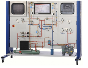
Inverter Air-Condition And Refrigerator Comprehensive Trainer


Description:

Features

  1. Practice-oriented model of a commercial refrigeration system
  2. Refrigeration and freezing chamber to investigate different methods for capacity control.
  3. Trainer mainly introduce the system structure and working principle of inverter air conditioner and indirect cooling, direct cooling refrigerator;
  4. The understanding and detection method of the inverter air conditioner components;
  5. The electrical control principle of inverter air conditioner and indirect cooling, direct cooling refrigerator.
  6. Trainer with intelligent fault assessment function.

Learning objectives/experiments

  1. Training of air conditioner
  2. Understanding the main components of refrigeration system
  3. The understanding and test of each component in electrical circuit
  4. Understanding the system structure of frequency conversion air conditioner
  5. Familiar with refrigeration, heating working principle of air conditioner
  1. Understanding the frequency conversion principle of frequency conversion air conditioner
  2. Circuit principle analysis of frequency conversion air conditioner each unit
  3. Judgment method of air conditioning system lack of Fluorine
  4. The judgment method of too much of refrigerant in system
  5. Power supply circuit fault of air conditioner
  6. Indoor unit +12V power supply circuit fault
  7. Indoor unit +5V power supply circuit fault
  8. Indoor unit pipeline temperature sensor fault
  9. Indoor unit environment temperature sensor fault
  10. Indoor unit reset circuit fault
  11. Remote receiver power supply fault
  12. Indoor fan power supply fault
  13. Buzzer power supply fault
  14. The circuit faults that indoor unit supply power for outdoor unit
  15. Indoor unit communication circuit fault
  16. Outdoor unit +15V power supply circuit fault
  17. Outdoor unit +12V power supply circuit fault
  18. Outdoor unit +5V power supply circuit fault
  19. Outdoor unit environment temperature sensor fault
  20. Outdoor unit pipeline temperature sensor fault
  21. Exhaust gas temperature sensor of compressor fault
  22. Four-way reversing valve supply circuit fault
  23. Outdoor fan supply circuit fault
  24. Outdoor unit supply circuit fault
  25. Training of refrigerator
  26. Understand the main components of refrigeration system
  27. System structure, working principle of direct cooling, indirect cooling refrigerator
  28. Electrical system working principle of direct cooling refrigerator
  29. Electrical system working principle of indirect cooling refrigerator
  30. The judgment of too much of refrigerant in system
  31. The judgment of insufficient refrigerant in system
  32. Complete machine power supply circuit fault of direct cooling refrigerator
  33. Lighting lamp power supply circuit fault of direct cooling refrigerator
  34. Direct cooling refrigerator temperature controller fault
  35. Complete machine power supply circuit fault of indirect cooling refrigerator
  36. Fan power supply circuit fault of indirect cooling refrigerator
  37. Defrosting timer fault of indirect cooling refrigerator
  38. Defrosting temperature controller fault of indirect cooling refrigerator


Description

  1. The components of a refrigeration circuit with refrigeration and freezing chambers are arranged clearly in the trainer.
  2. Solenoid valves enable the separate or parallel operation of the evaporators in the two chambers.
  3. The circuit is equipped with a capacity controller, a start-up controller and a combined pressure switch for the delivery and intake sides of the compressor.
  4. One heat exchanger each in the inlet of the two evaporators enables the super cooling of the refrigerant to be investigated for the efficiency of the process.
  5. The refrigeration capacity of the two individual chambers is controlled by a thermostat.
  6. The refrigeration chamber also features an evaporation pressure controller.
  7. There are two defrosting methods for the freezing chamber: an electric defrost heater and a hot gas defrosting where hot refrigerant is fed directly from the compressor in the opposite direction through the evaporator.
  8. The simulation of twelve different faults, such as e.g., faulty valves or clogged pipes


Specification/ Technical data

  1. The basic unit consists of Compressor – Hermetically sealed type (Kirloskar/ Danfoss or equivalent make) of capacity 1.0 TR provided with variable frequency drive (VFD) suitable for R 22/ R-134a/R404A refrigerant.
  2. Condenser - Fin & Tube type air cooled condenser (Copper tube, MS Fins) with Fan, variable speed motor and speed controller.
  3. Evaporator - Air cooled Evaporator (Copper tube, MS Fins) with two tapping and necessary valves at inlet and outlet with fan and variable speed motor.
  4. Expansion Device – Two type of expansion devices –Capillary tube and Thermostatic Expansion valve (Danfoss or equivalent make) with an arrangement to select any one type using solenoid valve.
  5. Air Flow - Variable speed Centrifugal/Axial Fan of suitable capacity.
  6. Heaters - Strip type electric heating element with Fins for Preheating and Reheating of 1 kW capacity.
  7. Humidifier - Boiler type Steam humidifier, fitted with variable voltage electric heater approx 5 KW with level indicator, pressure gauge, float level control and drain plug.
  8. Air Chamber - Duct made of Fiber glass with transparent Plexiglas covers with damper/shutter control for recirculation effect.

INSTRUMENTATION AND CONTROLS

  1. The basic unit consists of following instrumentation and control elements Temperature Measurement – Temperature thermocouples (08Nos) with digital electronic meter with output via RS port.
  2. Temp is recorded with an accuracy of 0.10C.
  3. Pressure Measurement - Pressure transducers (04 Nos) for electronic Operation and pressure gauges (04 Nos) for manual operation
  4. Refrigerant flow Measurement- Rota meter /refrigerant flow meter (01 no) Electronic flow meter/flow sensor (01 no).
  5. Power Measurement - Digital type Energy meters - one each for compressor and Condenser /Evaporator Fan, pre-heater and re-heater Digital Voltmeters and Ammeters - each for compressor power and condenser/evaporator fan power, Pre heater and re heater.
  6. Air flow Measurement - Orifice meter with pressure
    manometer for Manual operation Pressure transducer for electronic operation.
  7. Humidity Measurement - Electronic /Digital Psychometer
  8. Condensate Measurement - Graduated cylinder with drip tray
  9. Thermal Protection - Thermostats –each for preheater,
    re heater and humidifier boiler Separate safety device to be provided which should not allow Pre heater, re heater and humidifier boiler to operate unless air flow fan is on.
  10. Electrical Protection - Circuit breaker mounted on control panel to be provided for each major component.
  11. Filter/Drier - Danfoss or equivalent make System should be fitted with Sight Glass, Filters, HP/LP cutout
  12. Refrigerant Leak Detection – Electronic type leak detector to be provided.
  13. Unit consists of suitable number of
    service valves.
  1. Data acquisition system shall have following features
  2. Capable of measuring and recording of refrigerant mass flow rate, temperature and pressure data on real time basis.
  3. System shall be provided with genuine registered Software (Lab View 2016) capable of acquiring, analyzing and displaying
    temperature, pressure data, calculations related to refrigeration capacity, compressor power, Condenser/evaporator fan power, COP, p-H chart of refrigeration system on real time basis.
  4. Computer (DELL/SAMSUNG/HP/WIPRO or equivalent make) with Intel Pentium i-5 processor, 2.0 GHz, 500 GB HDD
    (7200 rpm), 4 GB DDR RAM,CD ROM Drive 64 X with CD/DVD writer complete with Window 7 and Antivirus, Color LCD monitor 17”, UPS system of 2.2 KVA, Color Laser Printer (SAMSUNG/ HP or equivalent make) 14 PPM.
  5. Digital clamp Meter 1No.
  6. Vacuum Pump: 1 Set
  7. Double Table Valve fluoride meter group.
  8. Metric Conversion Adaptor: 2 sets.
  9. Data Acquisition Card (National Instrument/equivalent make), 16 channel analog input, 01 channel analog output, 30
    MHz speed.
  10. Mimic of the plant with LED Panel.
  1. 230V, 50Hz, 1 phase
  2. Graphs 

Overall Dimensions and Weight

  1. LxWxH: 1465mm×820mm×1720mm Approx.
  1. Weight: approx. 106kg


Send us Enquiry


Visit Us

Office: S. N. 37/02, "Ashtavinayak Indl. Estate", Parvati Nagar, Dhayari Narhe Road, Next to Pari Robotics, Narhe, Pune-411041
Tel fax: (020) 24690312,
Email: sales@xeepl.com, xeepl.pune@gmail.com

Lets Visit

Become a Facebook Fan