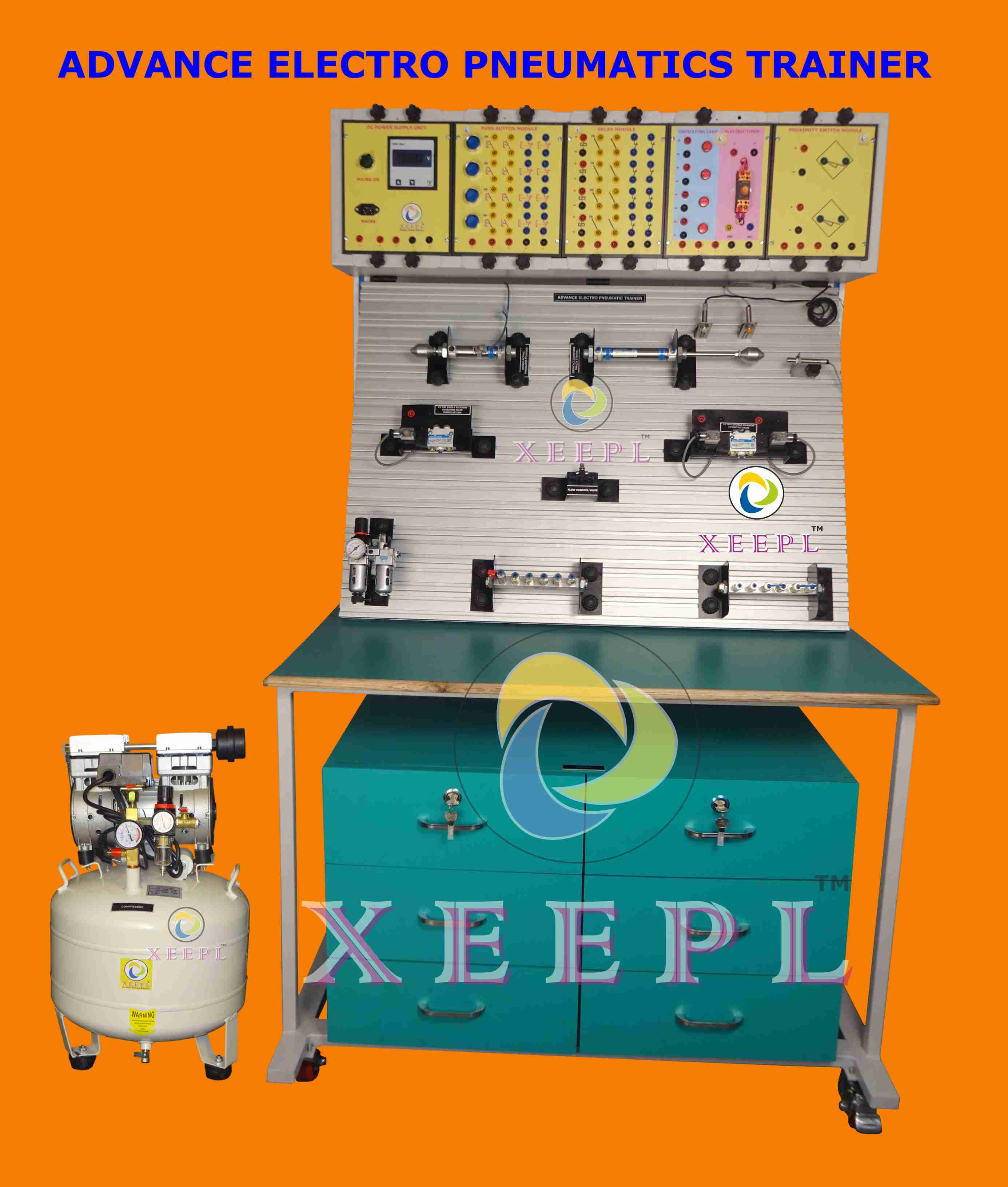
PNEUMATICS TRAINING SYSTEM


Description:

Learning Objectives/Experiments:

  •  PLC Programming Facility through P.C. 
  • Single acting cylinder automatic control,
  • Double acting cylinder automatic control,
  • PLC control technical application
  • Relay control technical application
  • Other comprehensiveness, expansibility experiment type pneumatic circuit.
  • Pneumatic basic experiment circuits illustrate:
  • Single acting cylinder reversing circuit,
  • Double acting cylinder reversing circuit,
  • Single acting cylinder speed control circuit,
  • Double acting cylinder one-way speed regulation circuit,
  • Double acting cylinder both-way speed regulation circuit,
  • Speed changing-over circuit,
  • Buffering circuit,
  • Twice pressure control circuit,
  • High and low voltage convert circuit,
  • Delay circuit,
  • Overload protection circuit,
  • Interlocking circuit,
  • Single cylinder single reciprocating control circuit,
  • Single cylinder continuous reciprocating action circuit,
  • Multi cylinder sequence action circuit
  • Double-cylinder synchronization action circuit,
  • Unloading circuit,
  • Or gate type valve shuttle application circuit,
  • And gate application circuit of double press valve,
  • Rapid exhaust valve application circuit,
  • Magnetic induction type proximity switch application;
  • Sensor application in control system;
  • Relay control circuit

Features:

  • This type of electrical pneumatic training device is at the request of modern pneumatic professional teaching experiment, according to “the hydraulic and pneumatic transmission “, “the pneumatic control technology”, etc., general teaching material contents design.
  • The system in addition to regular pneumatic basic control circuit experiment, still can be simulate the pneumatic control technology application experiment, pneumatic technology curriculum design, is the typical experiment equipment that the mechanical combine with electrical perfectly.
  • The system in Addition Meet the base and teaching training system of need of practical applications.
  • Equipment structure is firm and has good stability.
  • Low noise operation
  • layout clear and intriguing design.
  • The four truckles with crack slot in order to move and install on the work table. Panel grooves intervals are 25 mm, can easily move all kinds of components insert on it.
  • Various pneumatic components into separate module which is equipped with bottom panel of elastic pins, when training they can build all kinds of pneumatic circuits on general aluminium, fast loading and unloading, flexible layout, clear pneumatic circuit
  • Electrical control units used for independent relay control unit and multi-button unit control electrical, simple and clear!
  • High safety: have over-current protection the power supply will cut off as earth leakage exceed 30mA; the electrical control use DC 24v power supply, with over current protection, can prevent damage to the equipment caused by improper operation
  • system nominal pressure is 0.6MPa.


Specification/Technical data

  • DC power: input, AC220V, 50Hz/60 Hz Output: DC 24V/3A
  • Air compressor (basic equipment minimal machine): power: AC 220V±10% 50Hz/60Hz motor power: 600W
  • Nominal volume: 9L normal output voltage 0.7 MPa, noise degree: 66 dB
  • Groove interval: 25mm
  • Table top structure: 1
  • With crack slot truckle: 4
  • Relay module:
  • coil voltage: DC 24V;
  • contactor type: circuit common-NO-NC
  • Contact capacity: AC 240V/10A/DC24V/10A
  • Button module: Signal lamp power supply: DC 24V
  • Contact capacity: AC220V/1A DC24V/2A
  • Mechanical electrical life: 1 million times
  • Workbench experiment table Dimension:
  • 1360 (length)×650 (width)×1650 (height Aluminium panel dimension:1200×600
  • Manifold Block Working pressure:5MPa Max pressure:0.8MPa input: φ6 output:φ4; one-way
  • Double-acting cylinder Cylinder diameter:20mmstroke:100mmworking pressure range:1~1MPaa
  • Single-acting cylinder: diameter:20mm
  • stroke:100mm
  • working pressure
  • range:1~1MPa
  • 5/3 solenoid directional valve central vented: DC power:DC24V Working pressure
  • range:15~0.8MPa, Drive way: electric control
  • 5/2 single solenoid shuttle valve: voltage:DC24V Working pressure range:15~0.8MPa, Drive way: electric control
  • 5/2 double solenoid shuttle valve: 02 Nos
  • 3/2 single solenoid shuttle valve NC:01 Nos
  • 3/2 single solenoid shuttle valve NO: 01 Nos
  • 5/2 handle shuttle valve Mushroom button valves:01 No
  • 5/2 handle shuttle valve: 01 No
  • 5/3 handle shuttle valve: 01 No
  • Single pneumatic control 3/2: 01 No
  • Double pneumatic control 3/2: 01 No
  • Double pneumatic control 5/2: 02 Nos
  • Dyad:01 No (Pressure regulator:15~0.9MPa)
  • Reducing valve: 02 nos
  • One-way valve: 02 nos
  • Time delay valve:02 nos
  • Pressure gauge:02 nos
  • One-way throttle valve:02 nos
  • 3/2 knob valve:01 no
  • 3/2 Stroke valve:02 nos
  • Time delay valve:02 nos
  • Sequence valve:01 no
  • “And” gate-type dual pressure:02 nos
  • “Or” gate-type shuttle valve:02 nos
  • Quick escape valve:01 no
  • Micro switch valve (left trigger) :02 nos
  • Photoelectric Sensor:01 no
  • DC power supply unit: 01 No
  • DC power supply unit: 01 No
  • HoseФ4:100ft
  • 4 T Valve:03 Nos
  • Three connection:03 Nos
  • APG reducing straight coupling:03 Nos
  • Tool kits: 01 Set
  • Banana Jack: 01 Set
  • Ø  Pneumatic Pipe: 01 Coil

 NOTE: COMPUTER NOT IN OUR SCOPE OF SUPPLY

Dimensions and weight:

  • Dimension: 1360(length)×650 (width)×1650 (height Aluminium panel dimension:1200×600 Weight: approx. 100kg

Send us Enquiry


Visit Us

Office: S. N. 37/02, "Ashtavinayak Indl. Estate", Parvati Nagar, Dhayari Narhe Road, Next to Pari Robotics, Narhe, Pune-411041
Tel fax: (020) 24690312,
Email: sales@xeepl.com, xeepl.pune@gmail.com

Lets Visit

Become a Facebook Fan