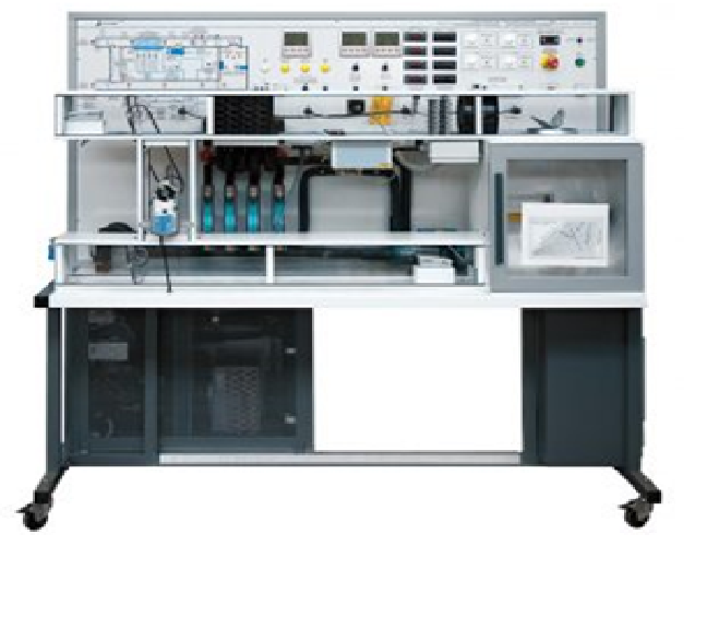
Computerized Air Conditioning Cycle Trainer


Description:

Learning Objectives/Experiments

  1. Recognize and study all the components used in the air conditioning system
  2. Study the state of refrigerant in the compression refrigeration cycle
  3. Study heating, cooling, humidification and dehumidification processes
  4. Determine the COP


Features

  1. The training equipment is built around an aluminum profile and a sheet metal frame that includes a silk screen panel with mounting components and a profile substrate for easy installation. The equipment undercarriage is equipped with casters with brake locks. Each system is fully equipped with piping and electrical connections so that it can be run at any time.
  2. The parts are clearly laid out and labeled for easy identification, providing a cooling schematic and schematic for the instructional teaching. The refrigeration line is coded in red and blue colors, red for high pressure, blue for low pressure to indicate the state of the refrigerant, and a sight glass to monitor the refrigerant's cooling state at that location.
  3. Refrigerant: R22 or equivalent
  4. Components and systems include:
  • Heating unit, cooler and dehumidifying unit. Sight glass, high and low pressure vacuum gauge, high and low voltage controller
  • Instrument control panel with voltmeter, ammeter, on/off control, circuit breaker with leakage protection device, overload protection device, key start switch, operation indicator, four temperature displays, controller, fan speed controller. All necessary controls and wiring. A schematic of all part labels showing the text and graphics of the cooling circuit.
  • RS485 information acquisition system: it can realize the interaction between the computer and the refrigeration system.
  • The data is transmitted to the computer through the RS485 information acquisition serial port.
  • The transmitted data includes voltage, current, phase angle, frequency, power, high and low pressure, time, etc.
  • Numerical value.
  • It also includes the system schematic diagram, which can be printed through the computer.


Specification/Technical data

  1. Power supply: single phase 220V ± 10%, 50Hz, 16A
  2. Test bench size (mm): 1500 (length) × 750 (width) × 1650 (height)
  3. Test bench body: movable steel platform with four casters (two with brakes and two without brakes).
  4. Sealed compressor Power supply: single phase 220V ± 10%
  5. Capacity: 1HP
  6. Refrigerant: R22
  7. Air cooled condenser
  8. Power supply: single phase 220V ± 10%
  9. Evaporator Power supply: single phase 220V ± 10% With fan
  10. Humidifier device
  11. Power supply: single-phase 220V±10%
  12. Capacity: 2.3 liters
  13. Heater Power supply: single-phase 220V±10%
  14. Power: 500W
  15. Evaporation box 1 Pc
  16. Liquid storage tank Capacity: 1L 1 Pc
  17. Manual valve
  18. Connection method: Flare threaded
  19. Connection size: Φ 6 3 Piece
  20. Temperature controller and Thermistor
  21. Power supply: single-phase 220V + 10%
  22. Heating control output: AC220V
  23. Cooling control output: AC220V
  24. Humidification control output: AC220V
  25. High pressure gauge Pressure: 0-3.8Mpa
  26. Connection mode: trumpet thread
  27. Connection pipe diameter: Φ 6 11 Low
  28. Pressure gauge Pressure: 0-1.8Mpa
  29. Connection mode: trumpet thread connection
  30. Connection pipe diameter: Φ 6
  31. Digital Temperature Display and Thermistor
  32. Power supply: single-phase 220V + 10%
  33. Temperature display range: - 50 +110
  34. Measurement accuracy: +0.5 C
  35. Display resolution: 0.1 Celsius
  36. Sensor: NTC, sheath lead
  37. 13 Speed regulator
  38. Input voltage: 220V
  39. Output voltage: 10-220v adjustable
  40. High Voltage Controller Low pressure controller
  41. Connection mode: trumpet thread connection
  42. Connection pipe diameter: Φ 6
  43. Observation mirror Welding type 1 Piece
  44. Solenoid valve
  45. Power supply: single phase 220V ± 10%
  46. Connection method: welding
  47. Leakage Circuit Breaker Protector
  48. Power supply: single phase 220V±10%
  49. Current: 16A
  50. Pressure transmitter sensor 0-2Mpa,4-20MA 2 Pcs DC power supply
  51. Power supply: single-phase 220V±10%
  52. Output current: 3A
  53. Output voltage: 24V
  54. Power monitoring module Power: 24V 1 Pc
  55. Analog input module Power: 24V 1 Pc
  56. Key switch Self-locking 1 Piece
  57. Emergency stop button Self-locking 1 Piece
  58. Pointer voltmeter 0~250v 1 Piece
  59. Pointer ammeter 0~10A 1 Piece
  60. Overload protector 10A 1 Piece
  61. Indicator lamp 5 Piece
  62. Manual 1 Set
  63. 230V, 50Hz, 1 phase

Dimensions and weight

  1. LxWxH: 600x520x460mm
  2. Weight: approx. 76kg


Send us Enquiry


Visit Us

Office: S. N. 37/02, "Ashtavinayak Indl. Estate", Parvati Nagar, Dhayari Narhe Road, Next to Pari Robotics, Narhe, Pune-411041
Tel fax: (020) 24690312,
Email: sales@xeepl.com, xeepl.pune@gmail.com

Lets Visit

Become a Facebook Fan