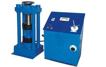

COMPRESSION TESTING MACHINE:
AS PER IS-516, B.S.S. 1610, 1881
INTRODUCTION:
Strength of Concrete is a very important aspect during construction. Strength of concrete Is obtained by crushing the specimen in form of cubes or cylinders. Concrete is carefully designed for a particular compressive strength by the Engineers and specimen is tested by applying load in a compression Testing Machine. Range of Compression Testing Machines from 10 Tons to 300 Tones in different models. Portable models are very convenient and useful for site use where carrying frequently the specimens for testing in a standard laboratory is inconvenient and uneconomical. With special attachments the machines can also be used for bricks. Hallow or solid concrete blocks, using appropriate capacity machine. In general a Compression Testing Machine consists of a Load Frame with suitable platens and a Pumping Unit with Pressure Gauge, either hand operated or electrically cum- hand operated or Digital or Computerized. Load Frame and Pumping unit are connected by pressure pipe.
PILLAR TYPE LOAD FRAME
OR
CHANNEL TYPE LOAD FRAME
Note: The platens are normally circular in shape, but on special request square platens or rectangular platens can be supplied.
ELECTRICALLY CUM HAND OPERATED PUMPING UNIT
Note:
Digital & Computerized versions of electrically operated Compression Testing Machines can also be supplied.
The digital versions have 0.5% accuracy Various Models of Compression Testing Machine are available listed in the following table.
|
MODEL |
150-HO-P |
150-EO-P |
150-HO-C |
250-HO-P |
250-EO-P |
500-HO-P |
500-EO-P |
1000-HO-P |
1000-EO-P |
1000-EO-C-2 |
1500-EO-P |
1500-EO-C |
2000-EO-P |
2000-EO-P-3 |
|
Cap. in KN |
150 |
150 |
150 |
250 |
250 |
500 |
500 |
1000 |
1000 |
1000 2-Gauge |
1500 |
1500 |
2000 |
2000 3-Gauge |
|
Readable to in KN |
0.75 |
0.75 |
0.75 |
1.25 |
1.25 |
2.5 |
2.5 |
5 |
5 |
0-250 x 1.25, 0-1000 x 5 |
7.5 |
7.5 |
10 |
0-500 x 2.5, 0-1000 x 5, 0-2000 x 10 |
|
Load Frame Type |
Pillar |
Pillar |
Channel |
Pillar |
Pillar |
Pillar |
Pillar |
Pillar |
Pillar |
Channel |
Pillar |
Channel |
Pillar |
Pillar |
|
Pumping Unit |
H/O |
Ele/H |
H/O |
H/O |
Ele/H |
H/O |
Ele/H |
H/O |
Ele/H |
Ele/H |
Ele/H |
Ele/H |
Ele/H |
Ele/H |
|
Ram Dia (mm) |
75 |
75 |
75 |
90 |
90 |
116 |
116 |
165 |
165 |
165 |
181 |
181 |
203 |
203 |
|
Max. Clearance Between Platens |
200 |
200 |
200 |
200 |
200 |
250 |
250 |
330 |
330 |
330 |
330 |
330 |
330 |
330 |
|
Platen Size |
100 |
100 |
100 |
125 |
125 |
150 |
150 |
180 |
180 |
180 |
180 |
180 |
225 |
225 |
|
Elec. Motor H.P. |
- |
1 |
- |
- |
1 |
- |
1 |
- |
1 |
1 |
1 |
1 |
1 |
1 |
Note: Standard Machines are supplied for operated for operation on 415 volts, Three phase, 50 H2 supply. Can be supplied for operation on 230 volts, single Phase, A.C. Supply on specifying, while placing orders, at extra cost
Office: S. N. 37/02, "Ashtavinayak Indl. Estate",
Parvati Nagar, Dhayari Narhe Road,
Next to Pari Robotics, Narhe, Pune-411041
Tel fax: (020) 24690312,
Email: sales@xeepl.com, xeepl.pune@gmail.com